Real Info About Can You Run MOSFETs In Parallel

Using Power MOSFETs In Parallel_drv3255CSDN博客
Parallel MOSFETs
So, you're pondering the question: Can you run MOSFETs in parallel? The short answer is, yes, absolutely! But, like most things in electronics, there's a bit more to it than just slapping a bunch of them together and hoping for the best. We're going to explore the ins and outs of paralleling MOSFETs, why you might want to do it, and the potential pitfalls that await the unwary. Think of it as a friendly guide through the MOSFET jungle.
1. Why Bother with Parallel MOSFETs Anyway?
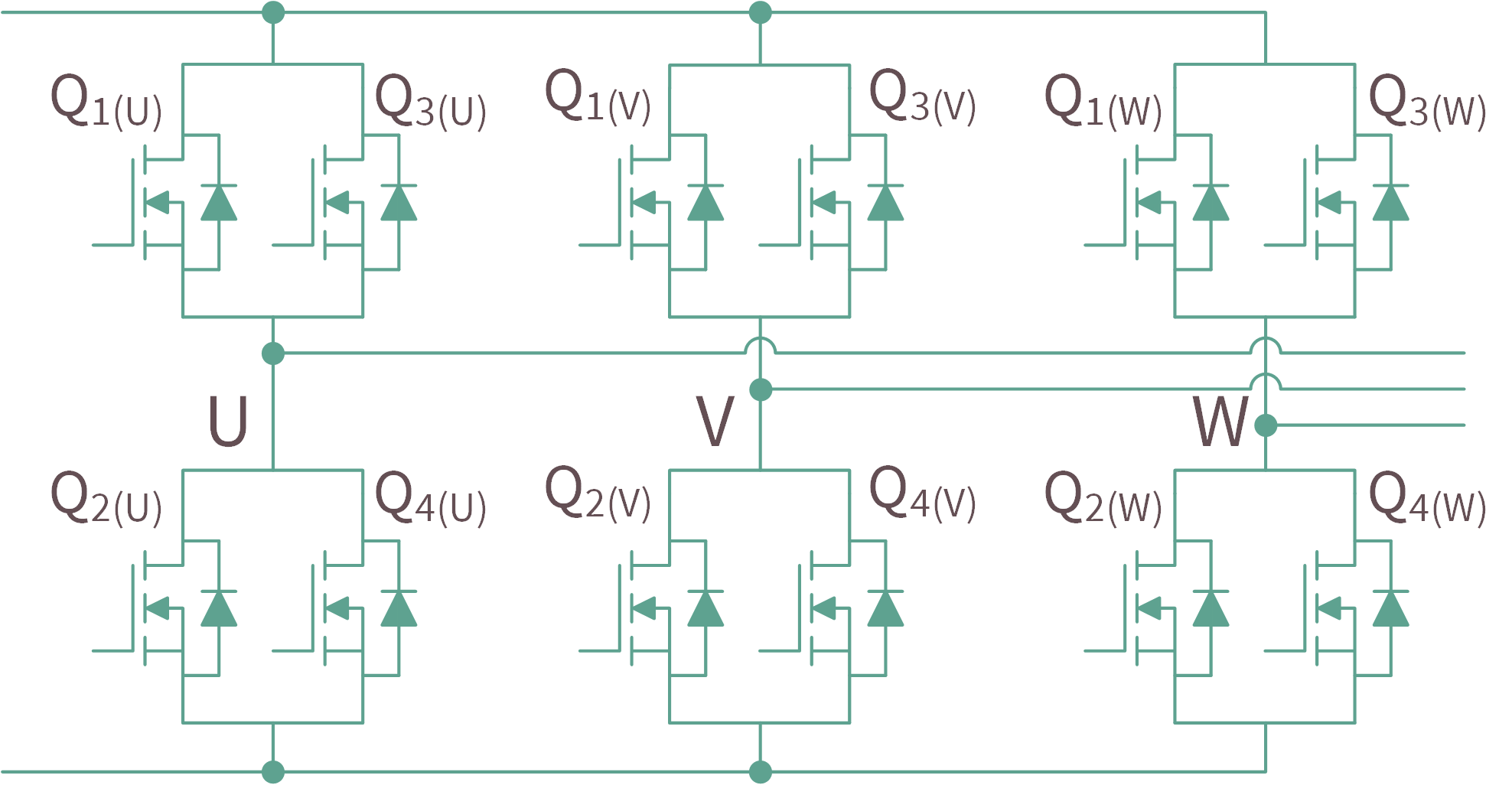
The main reason people consider paralleling MOSFETs is to increase the current handling capability of a circuit. One MOSFET might not be able to handle the amperage needed for a specific application. By connecting multiple MOSFETs in parallel, you effectively share the load, allowing the circuit to operate reliably at higher currents. It's like having a team of tiny, hardworking electronic helpers.
Another reason is heat dissipation. Each MOSFET has a certain thermal resistance, meaning it gets hotter as it dissipates power. By spreading the power dissipation across multiple devices, you reduce the temperature rise in each individual MOSFET. This can significantly improve the overall reliability and lifespan of your circuit. It's kind of like spreading butter on toast—thinner is better!
Sometimes, you might even find that paralleling MOSFETs is more cost-effective or space-efficient than using a single, larger MOSFET. This is especially true for high-volume applications where even small savings can add up significantly. Plus, using multiple smaller components offers redundancy; if one MOSFET fails, the others can still carry the load (albeit with reduced capacity).
But, it is important to note that while paralleling MOSFETs offer benefits, it does not increase the voltage rating of the combined setup. The voltage rating remains the same as the individual MOSFETs used.

The Crucial Consideration
2. The Dreaded Thermal Runaway
Here's the catch: MOSFETs are not all created equal. Even MOSFETs from the same batch can have slight variations in their characteristics, such as their threshold voltage (Vgs(th)) and on-resistance (Rds(on)). These variations can lead to unequal current sharing, where one MOSFET ends up carrying a disproportionately large share of the load. This can lead to overheating and, ultimately, thermal runaway—a fancy term for "your MOSFET blows up." No one wants that.
Think of it like a group of people carrying a heavy object. If one person is stronger or more enthusiastic than the others, they might try to carry more of the weight. If they carry too much, they'll get tired quickly, and the others will have to pick up the slack. In the MOSFET world, "tired" means "overheated and destroyed."
Thermal runaway occurs when a MOSFET starts to heat up, which causes its Rds(on) to decrease. This decrease in Rds(on) causes it to draw even more current, leading to further heating. This positive feedback loop can quickly escalate until the MOSFET exceeds its maximum temperature rating and fails. It's a vicious cycle!
To prevent this, you need to ensure that the current is shared as evenly as possible among the parallel MOSFETs. Luckily, there are several techniques you can employ to achieve this.

Driving Parallel MOSFET Individually General Electronics Arduino Forum
Techniques for Achieving Equal Current Sharing
3. Gate Resistors
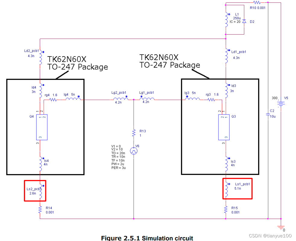
One of the simplest and most effective techniques for improving current sharing is to add small gate resistors in series with each MOSFET's gate. These resistors help to dampen oscillations and slow down the switching speed, which reduces the likelihood of current imbalances during transient conditions. A good starting point is to use resistors in the range of 10 to 100 ohms, but the optimal value will depend on your specific application.
The gate resistors also introduce a small amount of negative feedback, which helps to stabilize the current sharing. If one MOSFET starts to draw more current, the voltage drop across its gate resistor will increase, reducing the gate-source voltage and thus limiting the current. It's like a tiny, self-regulating system.
It is important that all gate resistors are as identical as possible. Matched resistors (with a tolerance of 1% or better) are ideal in this role.
Using gate resistors is the cheapest and easiest option to help with current sharing, but it is not the only solution.
4. Source Resistors
Another technique, which is typically used in conjunction with gate resistors, is to add small source resistors in series with each MOSFET's source terminal. These resistors provide a more direct form of current feedback, as the voltage drop across each source resistor is directly proportional to the current flowing through that MOSFET. This makes it easier to balance the currents between the different devices.
Source resistors provide a more direct current sharing method but are usually more expensive than gate resistors.
Typically values for source resistors are much lower than gate resistors, usually less than 1 ohm.
The primary downside of using source resistors is that they reduce the overall efficiency of the circuit, as they dissipate some power. However, the improvement in current sharing and reliability often outweighs this disadvantage, especially in high-power applications.

Layout Considerations
5. Symmetry is Your Friend
Even with gate and source resistors, the physical layout of your circuit can have a significant impact on current sharing. It's crucial to ensure that the traces connecting the MOSFETs are as symmetrical as possible. This means that the lengths of the traces from the power supply to each MOSFET should be equal, and the traces connecting the MOSFETs to the load should also be equal in length and width.
Any asymmetry in the layout can introduce parasitic inductances and resistances that can cause current imbalances. For example, if one MOSFET has a shorter path to the power supply than the others, it will tend to draw more current. Similarly, if one MOSFET has a wider trace to the load, it will experience less voltage drop and thus draw more current.
Think of it like a race track. If one lane is shorter or wider than the others, the racer in that lane will have an unfair advantage. In the MOSFET world, "advantage" means "more current and a higher risk of thermal runaway."
Use a star connection wherever possible. This means that all MOSFETS connect to a single point. This applies to both the gate drive, the power source, and the load.

FAQ
6. Q
A: Nope! The voltage rating stays the same as the individual MOSFETs you're using. Paralleling only helps with current handling and heat dissipation.
7. Q
A: If one MOSFET fails, the others will continue to carry the load, but they'll have to work harder. This could potentially lead to overheating or failure of the remaining MOSFETs if the circuit isn't designed to handle the increased current. It's always best to design with some margin for error.
8. Q
A: Generally, it's best to use identical MOSFETs from the same batch. Mixing and matching different types can lead to significant current imbalances and potentially damage the devices. If you absolutely must use different MOSFETs, carefully consider their characteristics and use appropriate current sharing techniques.
9. Q
A: While not always strictly necessary, it's highly recommended, especially for high-current or high-frequency applications. Gate and source resistors provide a simple and effective way to improve current sharing and prevent thermal runaway. Think of them as cheap insurance against disaster.
