Casual Info About What Will Happen If A Voltmeter Is Connected In Series With The Supply

Voltmeter Mishaps
1. Understanding Voltmeter Functionality
So, you're curious about what happens when a voltmeter gets a little lost? Specifically, when it's accidentally connected in series with the power supply instead of in parallel? Well, let's just say sparks might not fly (hopefully!), but you're definitely not going to get the reading you expect. To understand why, we first need a quick refresher on how voltmeters are supposed to work.
Voltmeters are designed to measure the potential difference — the voltage — between two points in a circuit. Think of it like measuring the height difference between two spots on a hill. To do this accurately, they need to be connected in parallel. This means that the voltmeter provides an alternate path for the current, but ideally, very little current should actually flow through the voltmeter itself. Why? Because we don't want the voltmeter to interfere with the circuit it's measuring!
A good voltmeter has very high internal resistance. This high resistance is what ensures that only a tiny amount of current will detour through the meter when it's connected in parallel. It's like having a super-wide, smooth detour route that most of the traffic ignores. This way, the voltmeter can accurately "sense" the voltage without significantly altering the circuit's behavior.
Now, imagine the opposite scenario. What if you've got a traffic detour with a huge speed bump? Nobody's going that way! This is analogous to our "voltmeter in series" situation. Stay with me, we're getting to the juicy part!

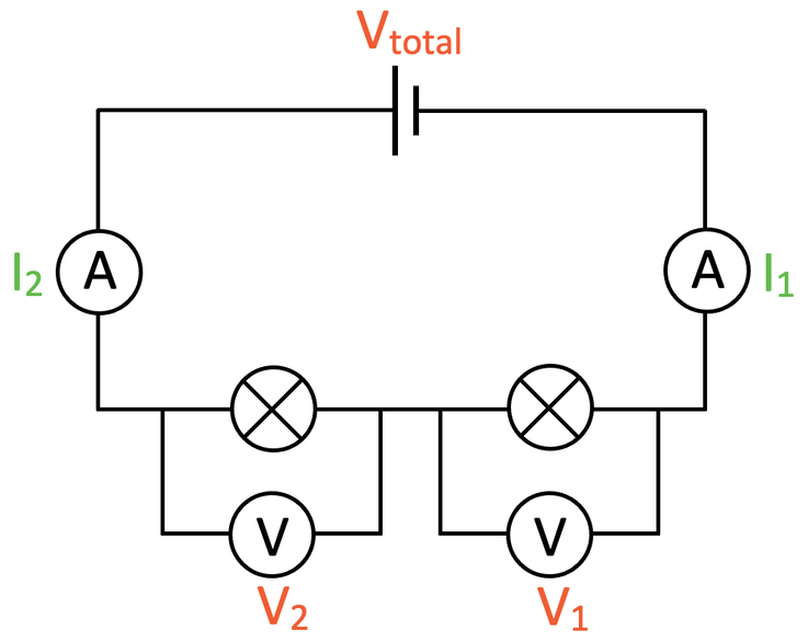
Voltmeter Circuit In Series At Sean Hawker Blog
The Series Snafu
2. Consequences of Incorrect Voltmeter Placement
Okay, picture this: You're setting up a circuit, and maybe you're a bit distracted, or perhaps youre having a Monday (we all have them!). Instead of connecting the voltmeter across the component you want to measure (in parallel), you accidentally wire it in line with the circuit (in series). What happens next?
The biggest consequence is that you've just introduced a huge resistance into your circuit. Remember, voltmeters are designed to have very high internal resistance. So, when you put that high resistance in the main path of the current, you're effectively choking off the flow. It's like putting a massive roadblock in the middle of a highway.
As a result, the current in the circuit will drop dramatically. In some cases, it might drop to almost zero. Think of it as the highway traffic being diverted down a tiny, barely-there side street. This drastic reduction in current can have a number of effects. The components in the circuit might not function properly (lights dimming, motors slowing down, etc.), and the voltage readings on the voltmeter itself will likely be way off. It might show close to the source voltage depending on the other resistances in the circuit.
Depending on the power supply's current limit and the voltmeter's tolerance, the voltmeter might even get damaged. Although most modern digital multimeters have overload protection, its best not to test the theory. It's generally a bad day for everyone involved if you try to make a voltmeter carry a significant current that it's not designed for. So, double check your connections before powering up your circuit!

Why the Reading is Wrong (So, So Wrong)
3. Understanding the Voltage Distribution
Let's delve a bit deeper into why the voltmeter reading is so unreliable when connected in series. The voltage reading you get is now essentially a representation of the voltage drop across the voltmeter's internal resistance. It's not reflecting the voltage of the component you intended to measure.
Think of voltage like water pressure in a pipe. If you put a very narrow section in the pipe (representing the high resistance of the voltmeter), most of the pressure drop will occur at that narrow section. The voltmeter is now measuring the "pressure difference" across that narrow section, not the pressure at other points in the pipe (i.e., the circuit components).
Furthermore, the introduction of the voltmeter into the circuit changes the entire circuit's behavior. The original voltage distribution is completely altered. The components that were supposed to have a certain voltage across them now have significantly less, because most of the voltage is being "consumed" by the voltmeter's resistance.
In essence, you're not measuring the intended circuit anymore. You're measuring a modified circuit where the voltmeter's presence dominates the voltage distribution. The voltmeter reading, in this setup, becomes a misleading piece of information, leading you to incorrect conclusions about the actual circuit performance.

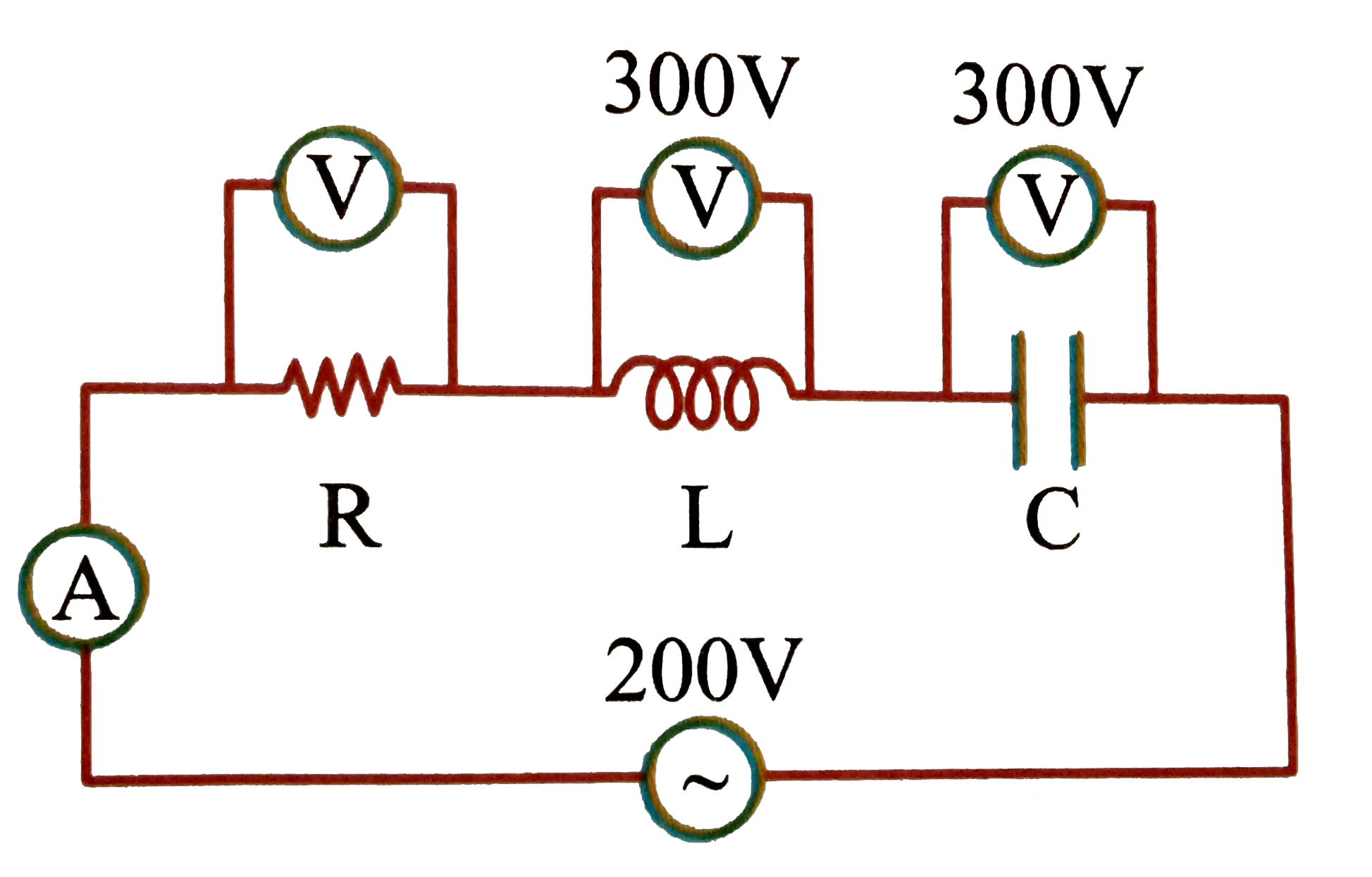
The Circuit Below Consists Of A Variable Resistor Connected In Series
Potential Damage and Safety First!
4. Risks Associated with Incorrect Connection
While the most likely outcome is a drastically reduced current and a wonky voltage reading, there's always a chance of things getting a little spicy. It's rare, but let's talk about why.
First, let's consider what happens if your power supply is capable of delivering a lot of current, even when faced with a high resistance. While the voltmeter should have a high resistance, there's always a limit. If the power supply tries to force too much current through the voltmeter, the internal components of the meter could overheat. This could lead to damage, potentially rendering the voltmeter useless, or worse, causing a small fire.
Second, if the voltmeter is an older analog type, the excessive current could damage the delicate needle movement mechanism. These older meters are less robust and more susceptible to damage from overcurrent situations.
Third, and most importantly, always remember that electricity can be dangerous. While this particular scenario might not be immediately life-threatening, incorrect wiring can lead to other more hazardous situations. Always disconnect the power source before making changes to a circuit. Double-check your connections, and when in doubt, ask for help from someone with more experience. Electrical safety is paramount!

Parallel vs. Series
5. Reinforcing Correct Voltmeter Usage
Let's reiterate the most crucial point: Voltmeters are always connected in parallel. Think of it like taking a small detour to measure the voltage, without disrupting the main flow of current.
To connect a voltmeter in parallel, identify the two points in the circuit across which you want to measure the voltage. Then, connect one lead of the voltmeter to one of those points, and the other lead to the other point. The voltmeter creates a parallel path, allowing it to sense the voltage difference without significantly affecting the circuit's operation.
Connecting a voltmeter in series, on the other hand, is a big no-no. It's like trying to force all the traffic through a tiny tollbooth. It will drastically reduce the current, give you a wrong reading, and potentially damage the voltmeter or the circuit. This is especially true for analog voltmeters.
So, remember the golden rule: Parallel for voltage, series for well, nothing involving voltmeters! Stick to that, and you'll avoid a lot of headaches (and potential electrical mishaps).

Voltmeter In A Series Circuit
FAQ
6. Question
Answer: It's unlikely to damage a modern power supply, especially one with built-in current limiting. The power supply will likely just reduce its output voltage to try and maintain the set current limit. However, older, unregulated power supplies could be stressed, potentially shortening their lifespan. It's best to avoid the situation altogether.
7. Question
Answer: Ouch! That's a potentially much more dangerous situation. Ammeters are designed to have very low resistance, so connecting one in parallel creates a short circuit. This can cause a large, potentially damaging current to flow, possibly blowing a fuse, damaging the ammeter, or even causing a fire. Always double-check your ammeter connections!
8. Question
Answer: It depends! If the resistance in the rest of the circuit is very low and the power supply is pushing a significant voltage, it might. Or, the voltage drop across the voltmeter (due to its high resistance) might be so high that it exceeds the voltmeter's maximum input voltage, resulting in an "OL" display. If the current is sufficiently limited by the voltmeter's resistance, it may give some reading, albeit inaccurate.