Best Of The Best Info About What Happens To Potential Difference In A Series Circuit

Potential Difference Formula In A Circuit
Understanding Potential Difference in a Series Circuit
1. What's Potential Difference Anyway?
Ever wondered what makes your gadgets tick? It all boils down to electricity, and at the heart of it is potential difference, also known as voltage. Think of it like the pressure that pushes water through a pipe. In an electrical circuit, potential difference is the "pressure" that drives electrons, creating an electric current. Measured in volts (V), it's the difference in electrical potential energy between two points in a circuit. No volts, no flow, no fun! It's what allows your devices to do all the amazing things they do.
Without potential difference, your circuits would be as useful as a screen door on a submarine. Imagine trying to power your phone with no voltage; itd just sit there like a paperweight. This difference in electrical potential is crucial for getting those electrons moving and powering your favourite devices. So, next time you plug something in, give a little thanks to the potential difference doing its thing!
Now, let's get specific. A series circuit is a circuit where components are connected one after the other, forming a single path for the current to flow. Think of it like a single lane highway. Understanding what happens to potential difference in this type of circuit is fundamental to grasping how electricity works.
Think of a string of old-fashioned Christmas lights. If one bulb goes out, they all go out. That's a series circuit in action (or inaction!). Each light bulb offers resistance to the flow of electricity. And now, let's see what happens to that voltage as it passes through each light bulb.

Potential Difference Division in a Series Circuit
2. The Voltage Drop
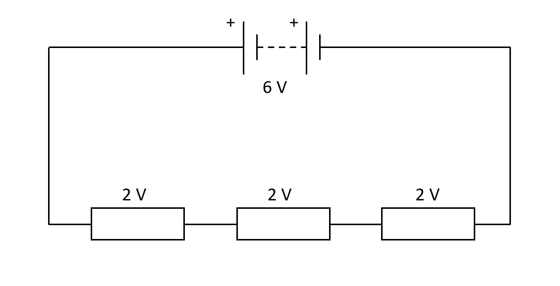
Here's the key concept: in a series circuit, the total potential difference supplied by the source (like a battery) is divided among all the components in the circuit. Each component "consumes" some of the voltage as the current passes through it. This "consumption" is known as a voltage drop.
Imagine you have a 9V battery powering three resistors in series. The 9V is not going to be evenly distributed, unless the resistors have the same resistance! Each resistor will have a "voltage drop" across it, and those individual voltage drops will add up to the total of 9V. Its like sharing a pizza each slice represents a voltage drop, and all the slices together make up the whole pizza (the total voltage).
The amount of voltage drop across each component depends on its resistance. Components with higher resistance will have a larger voltage drop. This makes sense, right? It takes more "pressure" (voltage) to push the current through a component that's resisting the flow more strongly.
Think of it like this: imagine you're trying to push a box through a narrow doorway. The narrower the doorway (higher resistance), the more effort (voltage) you need to put in. Now, imagine pushing that box through a series of doorways, each with a different width. Each doorway will require a certain amount of effort, and the total effort you exert will be the sum of the effort needed for each doorway.

Series Circuits Physics Explanation & Exercises Evulpo
Calculating Potential Difference
3. V = IR, Your New Best Friend
Fortunately, we don't have to guess how much voltage each component will drop. We can use Ohm's Law! Ohm's Law states that the potential difference (V) across a component is equal to the current (I) flowing through it multiplied by its resistance (R). The formula is simple: V = IR.
In a series circuit, the current (I) is the same throughout the entire circuit because there's only one path for the electrons to flow. So, to find the voltage drop across each component, you just need to know the current and the resistance of that component. Once you know those two values, you can plug them into Ohm's Law and find the voltage drop.
For example, let's say you have a 2-ohm resistor in a series circuit with a current of 1 amp flowing through it. Using Ohm's Law (V = IR), the voltage drop across the resistor would be V = (1 amp) * (2 ohms) = 2 volts. See? Easy peasy!
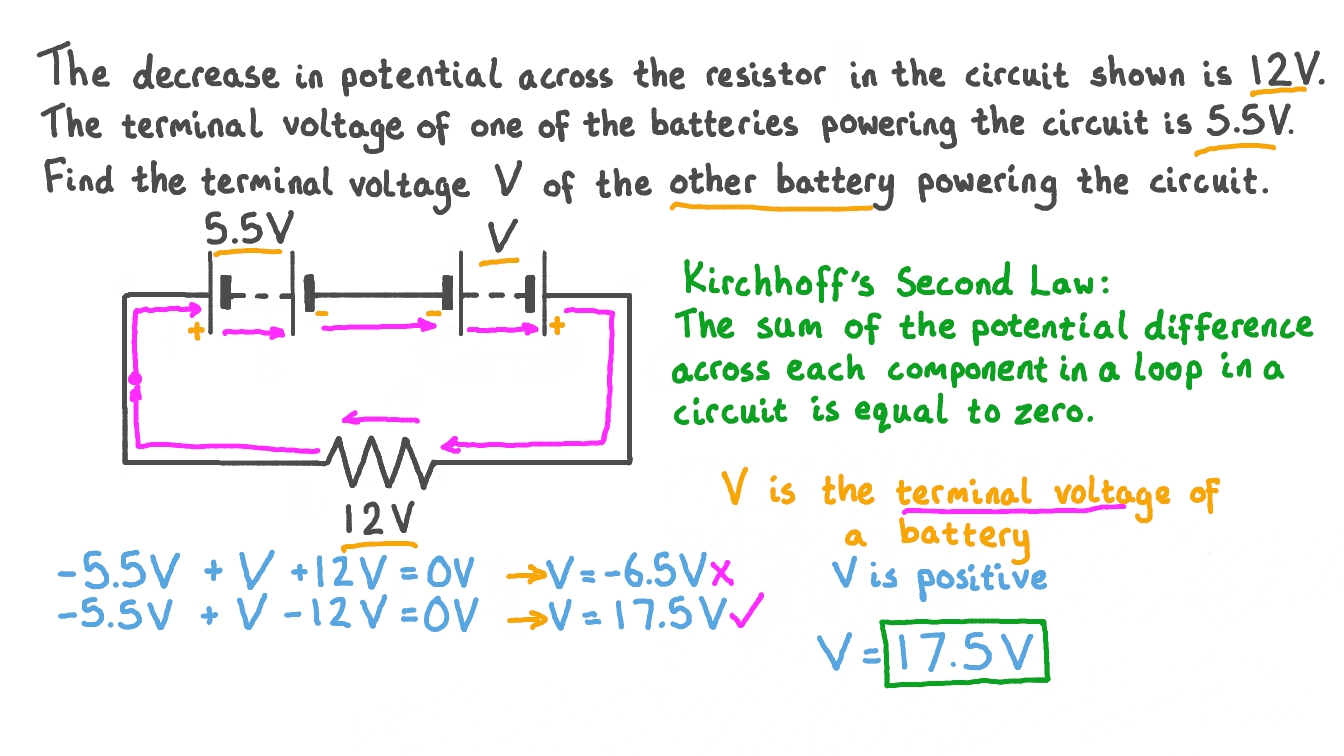
Let's say you are dealing with three resistors with different resistances. Remember that the total voltage must always be the sum of the individual voltage drops. So, if you know the total voltage and the voltage drops across two resistors, you can easily calculate the voltage drop across the third resistor by subtracting the known voltage drops from the total voltage.
![[ANSWERED] In A Series RLC Circuit Potential Differences Across R L And [ANSWERED] In A Series RLC Circuit Potential Differences Across R L And](https://media.kunduz.com/media/sug-question-candidate/20210802045906649849-2768793.jpg?h=512)
[ANSWERED] In A Series RLC Circuit Potential Differences Across R L And
Practical Implications of Potential Difference Division
4. Why This Matters in the Real World
Understanding potential difference division in series circuits isn't just an abstract concept. It has important practical implications. For example, when designing electronic circuits, engineers need to carefully consider how the voltage will be divided among the components to ensure that each component receives the correct voltage to operate properly. In the old Christmas light scenario, if one bulb burns out (infinite resistance) it will take all the voltage, so the other bulbs get none.
Consider the situation of LED's in series. LED's (light-emitting diodes) have very specific voltage requirements. Connecting too many LED's in series with a voltage source that isn't high enough can lead to them not lighting up at all, because each LED needs a certain "slice" of the voltage pizza. On the other hand, if the voltage source is too high, they can get burned out immediately!
Another practical application is in voltage dividers. A voltage divider is a simple circuit that uses two or more resistors in series to create a specific voltage at a certain point in the circuit. These circuits are commonly used in electronic devices to provide different voltage levels for different components.
In essence, understanding potential difference in series circuits allows us to design and troubleshoot electrical systems effectively, ensuring that everything runs smoothly and efficiently. From powering our homes to operating complex machinery, it's a fundamental principle that underpins much of the technology we rely on every day.

Potential Difference and Power Dissipation
5. The Power Equation
Now, let's bring in another critical concept: power dissipation. Each component in a series circuit not only experiences a voltage drop but also dissipates power. This power is usually dissipated as heat. The amount of power dissipated by a component is related to the voltage drop across it and the current flowing through it. The equation for power (P) is: P = VI.
So, a component with a higher voltage drop and a higher current flowing through it will dissipate more power. This is why resistors often get hot when current flows through them. They are converting electrical energy into heat energy. Its like a tiny electrical heater!
In a series circuit, because the current is the same throughout, components with higher resistance will dissipate more power. This is because they have a higher voltage drop across them. Understanding power dissipation is important for preventing components from overheating and failing. Engineers use heat sinks to dissipate heat from components that generate a lot of power. Overheating can also affect the long-term stability of components.
So, the next time you touch an electronic device and it feels warm, remember that's power dissipation in action. It's a fundamental aspect of how electrical circuits work, and understanding it helps us design safer and more efficient electronic systems.

FAQs About Potential Difference in Series Circuits
6. Quick Answers to Common Questions
Got more questions? Here are some quick answers to frequently asked questions about potential difference in series circuits:
Q: What happens to the current in a series circuit?
A: The current is the same throughout the entire series circuit. This is because there's only one path for the electrons to flow.
Q: How do I calculate the total resistance in a series circuit?
A: To calculate the total resistance in a series circuit, you simply add up the individual resistances of all the components: Rtotal = R1 + R2 + R3 + ...
Q: What happens if one component fails in a series circuit?
A: If one component fails (like a light bulb burning out), the entire circuit is broken, and current stops flowing. This is because there's only one path for the current, and if that path is interrupted, the circuit no longer works. That's why those old Christmas lights are so annoying! In the practical sense, the failed component's resistance is considered infinite, and will take all the potential difference.
Q: Does the order of the resistors matter in series circuit?
A: No, the order of the resistors in a series circuit does not affect the total resistance or the current flow. As long as the resistors are connected in series, the total resistance will be the sum of the individual resistances, regardless of their order.