Here Is A Quick Way To Solve A Info About How Does A MOSFET Act As Capacitor

Mos As A Capacitor At Sophie Clarkson Blog
Decoding the MOSFET
1. Understanding the Layers Underneath
So, you're curious about how a MOSFET, that tiny workhorse in countless electronic gadgets, can act like a capacitor? It's a fair question! We usually think of MOSFETs as switches, turning current on and off. But lurking beneath that functionality is a hidden capacitive nature. Think of it as a double life; superhero by day, mild-mannered capacitor when you least expect it.
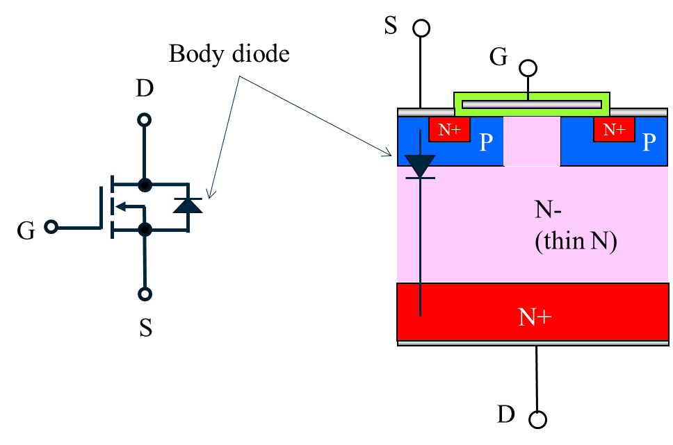
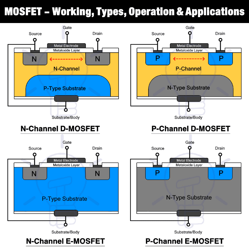
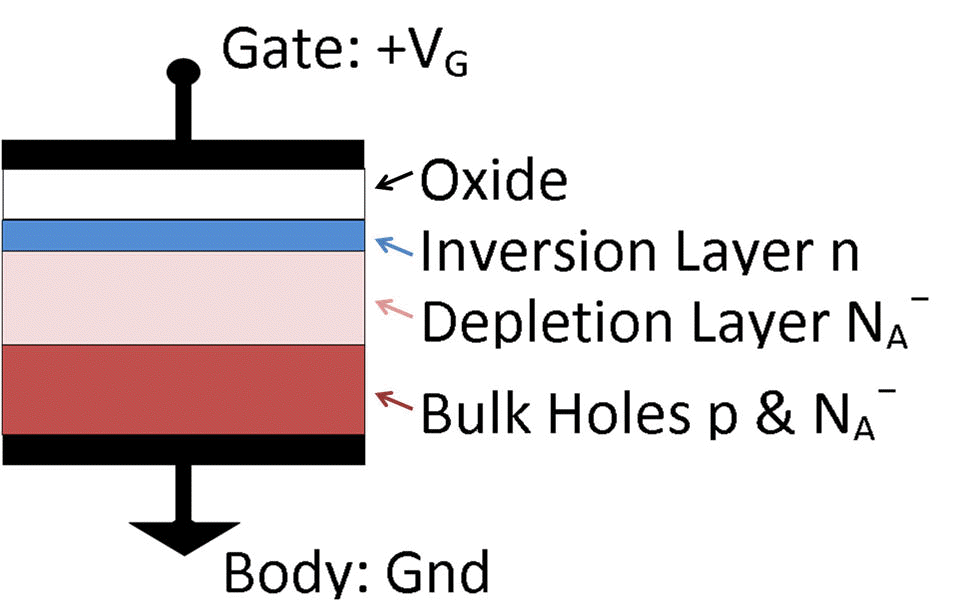
The key to understanding this duality lies in the MOSFET's structure. Imagine a sandwich. You've got the silicon substrate as the base, then a layer of insulation (usually silicon dioxide think of it as a super-thin glass), and finally the metal gate. This Metal-Oxide-Semiconductor stack is where the magic happens. And guess what that looks like? Ding ding ding! A capacitor!
That insulating layer, the oxide, acts as the dielectric, separating the conductive gate and the semiconductor substrate. Apply a voltage to the gate, and charges accumulate on either side of the oxide layer, just like in a regular capacitor. Different voltages will cause different accumulation of charges, that's the key to MOSFET's characteristic.
It's not a perfect capacitor, mind you. It's more like a leaky one, and the capacitance value isn't constant. It depends on the voltage applied and the operating region of the MOSFET. But the fundamental principle is there: separated charges, potential difference, ergo, capacitance!

Capacitive Elements Within the MOSFET
2. Unpacking the Various Capacitances
Okay, so we've established that the MOSFET can act like a capacitor, but it's not quite that simple. It's more accurate to say that MOSFETs contain various parasitic capacitances due to their physical structure. These aren't intentionally designed, but they're unavoidable consequences of the manufacturing process. Think of them as unwanted houseguests that you have to learn to live with.
The most important of these capacitances are the gate-source capacitance (Cgs), the gate-drain capacitance (Cgd), and the gate-bulk capacitance (Cgb). Each of these arises from the overlapping areas between the gate and the respective terminals of the MOSFET. Each of these acts in slightly different ways, at different times, and will be determined by different operation parameters.
Cgs is formed between the gate and the source region. It's relatively constant and predictable when the MOSFET is in the 'on' state. This is because when the MOSFET is turned on, a channel is formed between the source and drain, and the gate capacitance couples to the source through this channel.
Cgd is the gate-drain capacitance, also known as the Miller capacitance. This is where things get interesting! It's formed between the gate and the drain region and has a significant impact on the high-frequency performance of the MOSFET. The Miller effect amplifies the impact of Cgd on the overall circuit, making it a crucial factor to consider in high-speed designs.
Finally, Cgb exists between the gate and the bulk (or body) of the MOSFET. While it's often smaller than the other two, it's still present and can play a role in certain circuit configurations, especially at higher frequencies.

Mosfet Transistor
The Miller Effect
3. A Deep Dive into Gate-Drain Capacitance
We touched on the Miller effect earlier, but it's so important, it deserves its own section. Imagine you're trying to push a swing, but someone is pulling it back every time you push. That's kind of what the Miller effect does to the gate-drain capacitance. It effectively amplifies the capacitance, making it seem much larger than it actually is.
This amplification happens because the gate-drain capacitance is connected between the input (gate) and the output (drain) of the MOSFET. Any voltage change at the output (drain) is fed back to the input (gate) through this capacitance, creating a feedback loop. This feedback loop effectively multiplies the capacitance by a factor related to the gain of the MOSFET. Ouch!
So, why is this a problem? Well, a larger capacitance means a slower response time. It takes longer to charge and discharge the capacitor, which limits the maximum frequency at which the MOSFET can operate effectively. This is a major concern in high-speed circuits and radio frequency (RF) applications. If you're designing a high-speed amplifier, the Miller effect is your nemesis.
However, the Miller effect isn't always a bad thing! In some cases, engineers intentionally use it to create larger capacitances in their circuits, eliminating the need for external capacitors. It's all about understanding the effect and using it to your advantage. It's like turning your weakness into a strength!

Why Should I Care About These Capacitances?
4. Practical Implications and Real-World Applications
Okay, so all this talk about capacitances and the Miller effect might seem a bit abstract. But trust me, it has real-world implications. Understanding these parasitic capacitances is crucial for designing stable and high-performance circuits. Ignoring them is like ignoring the weather forecast — you might get caught in a storm!
Consider a simple amplifier circuit. The gate-drain capacitance can cause unwanted feedback, leading to oscillations and instability. This is why careful circuit design is essential to compensate for these effects, often by adding compensation capacitors or resistors to counteract the Miller effect.
In digital circuits, the gate capacitance affects the switching speed of the MOSFET. The larger the capacitance, the longer it takes to charge and discharge the gate, which slows down the switching time. This is why minimizing gate capacitance is a major goal in high-speed digital design.
In RF circuits, these capacitances become even more critical. They can significantly impact the impedance matching and performance of amplifiers, mixers, and other RF components. Accurate modeling and simulation of these capacitances are essential for achieving optimal performance. So, knowing how MOSFETs behave as capacitors is quite important to create better electrical circuits.
Essentially, understanding these capacitive behaviors allow electrical engineers to build precise and functional circuits that can operate at the specifications for the project.

MOSFET Working, Types, Operation, Advantages & Applications
Taming the Capacitive Beast
5. Mitigating the Effects of Parasitic Capacitances
Alright, so we know these parasitic capacitances exist and can cause problems. What can we do about it? Fortunately, there are several design techniques that engineers use to mitigate their effects. Think of it as having a toolbox full of tricks to tame the capacitive beast.
One common technique is to use smaller MOSFETs. Smaller devices generally have lower capacitances, which can improve the switching speed and reduce the Miller effect. However, there's a trade-off: smaller MOSFETs also have lower current carrying capability, so you have to choose the right size for your application.
Another technique is to use cascode amplifiers. A cascode amplifier uses two MOSFETs in series to reduce the Miller effect and improve the bandwidth of the amplifier. The first MOSFET acts as a common-source amplifier, while the second MOSFET acts as a common-gate amplifier, effectively isolating the input from the output and minimizing the feedback through the gate-drain capacitance.
Careful layout design is also crucial. Minimizing the overlap between the gate and the other terminals can reduce the parasitic capacitances. Shielding the gate from the drain can also help reduce the Miller effect. It's all about being smart and strategic about how you arrange the components on the circuit board.
Finally, using compensation techniques, such as adding compensation capacitors or resistors, can help stabilize the circuit and prevent oscillations. These techniques involve carefully selecting the values of the components to counteract the effects of the parasitic capacitances and ensure stable operation.
